Magnifications of stand magnifiers
Purpose. The aim of this study is to determine the achievable magnifications of stand magnifiers for a range of distances (distance between magnifier and eye) of 30 cm to 2 cm and the required near addition.
Material and Methods. On the optical bench, the magnification factor and the position of the magnified image were determined for 31 different magnifying glasses using a reflex camera. This allowed the magnification achieved to be calculated as a function of the distance between the magnifying glass and the eye. The position of the magnified image can also be used to determine the necessary ear addition, taking into account the distance between the magnifying glass and the eye.
Results. Stand magnifiers exhibit distance-dependent magnification, requiring an appropriate near addition for comfortable use. At a working distance of 30 cm, effective magnification was limited to 44 - 70 % of the nominal value, with a corresponding near addition of +1.5 to +2.0 D. Maximum magnification, approximating or slightly exceeding the nominal, was achieved only at a minimal object distance of 2 cm, necessitating substantially higher near additions of +4.0 to +6.0 D.
Conclusion. When choosing a suitable stand magnifier, it would be useful for low-vision specialists if manufacturers provided both the magnification factor and the distance of the magnified image for each stand magnifier. This information would make it easy to estimate the actual magnification achieved and determine the appropriate near addition for any given working distance.
Introduction
Reading magnification
According to estimates, 216.6 million people worldwide live with moderate to severe visual impairment (visual acuity 6/18 but 3/60 or better); 36 million people are considered blind.1 People with visual impairments usually rely on magnifying visual aids for reading.2 With visual acuity below a visual acuity of 6/12, normal newspaper print is usually no longer fluent and effortless to read.3 There is therefore a need for magnification. However, this does not depend exclusively on visual acuity, but can also be influenced by other factors, such as the size and location of scotomas in the central field of vision. Fröhlich 4 has shown, for example, that patients with age-related macular degeneration (AMD), who had similar visual acuity, have a higher average magnification requirement than patients whose visual impairment was caused by diabetic retinopathy. With an average near vision acuity of 6/30 in both groups, the magnification (requirement) for AMD patients was 7 times higher on average (median 3 times) and 4 times (median 2.5 times) for diabetes patients.
Various test charts with reading texts in logarithmically graded font sizes are available for the specific measurement of magnification requirements (e. g., the “Schweizer Test for Determining Magnification Requirements for Near Vision”). Once the magnification requirement has been determined, a suitable magnifying visual aid can be selected and tested. About 80 % of magnifying visual aid fittings are used to restore reading ability.3
Characteristics of stand magnifiers
Magnifying glasses are available in various designs, both with and without lighting.5 The refractive powers (D) of magnifying glasses used in the low vision sector range from approximately 6 D to approximately 56 D, whereby the higher the refractive power, the smaller the diameter of the magnifying glass and thus the field of vision. Magnifying glasses are placed directly on the object (y) to be magnified, usually a piece of text. The stand magnifier then produces a virtual, magnified, upright image (y’). Figure 1 shows the relevant (optical) distances when using a magnifying glass.
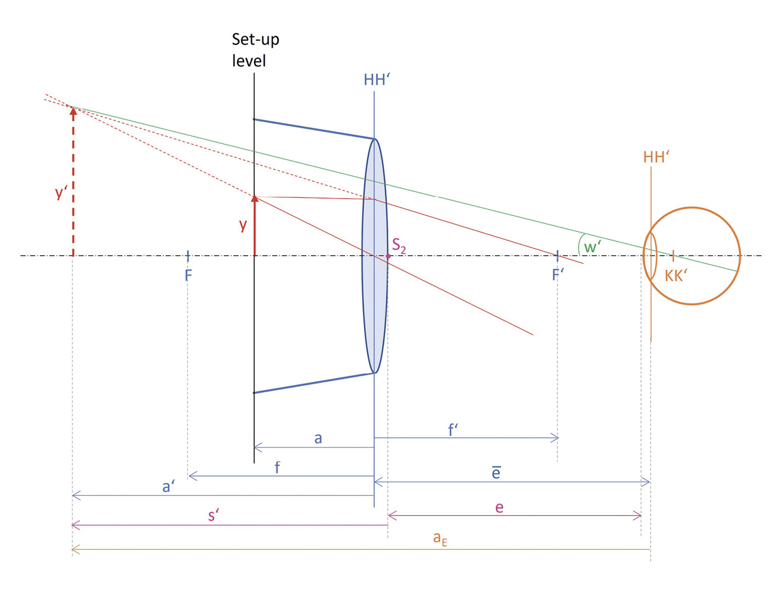
Since the object distance (a) of a stand magnifier is predetermined, its corresponding image distance (a’) is also fixed. The stand magnifier thus has a defined magnification scale (β‘). This is calculated as the quotient of the image size y’ and the object size y or the image distance a’ and the object distance a. The following applies:
β‘ = y‘ / y = a‘ / a(1)
Stand magnifiers are designed so that the magnifier-to-object distance is within the single object-focal length f. This was also the case for all stand magnifiers examined here. The magnified image is thus at a finite distance in front of the eye. Emmetropic individuals or those with fully corrected refractive errors must either be able to accommodate to the image produced by the magnifier or wear glasses with a suitable near addition (Z). The accommodation requirement or the necessary near addition is calculated as the reciprocal of the focusing distance (aE). Since the majority of people with visual impairments are presbyopic, it is usually necessary to provide suitable reading glasses together with the stand magnifier, or at least to ensure that existing reading glasses are suitable for the prescribed stand magnifier.
The magnifying glasses used by visually impaired people usually have aspherical plastic lenses (as do high-quality hand magnifiers), are therefore relatively light, and have significantly fewer imaging errors than the magnifiers with spherical surfaces that were used in the past.6 The way in which stand magnifiers are used is beneficial for people who, for example, suffer from hand tremors or have reduced manual coordination.7 Even people without tremors or other limitations may find it helpful when the stand magnifier rests steadily on the document and does not have to be held at the correct distance above the text all the time. Stand magnifiers used in low vision frequently contain an integrated LED lighting function. This can be advantageous for patients who report an increased need for light when reading due to their eye condition.
According to Grein, illuminated stand magnifiers are part of the “standard care” for many visually impaired people.7 Some stand magnifiers also have a semi-open design, so that it is possible to write or even work under the stand magnifier, albeit this is usually only possible to a limited extent.3 In some cases, it may be feasible to work under a stand magnifier if it is placed on the edge of a table. For example, an insulin pen could be placed underneath and read.
Magnification of stand magnifiers
Magnifiers are often specified with what is known as normal magnification Γ’N. This is sometimes printed directly onto the magnifier or can be found in the manufacturers’ instrument manuals. Normal magnification is calculated using the refractive index D of the magnifier with:
Γ‘N = D / (4 dpt)(2)
However, the normal magnification formula is only valid for two specific situations. Either the object (the text) must be at the object-side focal point F of the magnifier, or the eye must be at the image-side focal point F’ of the magnifier.8 Since stand magnifiers are designed so that the magnifier to object distance is within the object-side focal length (Figure 1), the first situation cannot occur unless the magnifying glass is lifted while reading. The second situation (eye at the image-side focal point of the magnifier) is possible, but relatively unlikely, as the distance between the magnifier and the eye would have to be very small. For example, with a 12 D stand magnifier, a distance of approximately 8 cm (f’ = 1/12 D = 0.08 m) between the stand magnifier and the eye would have to be maintained, and with even stronger magnifiers, correspondingly shorter distances.
However, since stand magnifiers are usually used from a comfortable sitting position at a table, the distances between the magnifier and the eye are usually much greater than the focal lengths of the magnifier. The magnifications achieved are then lower than the normal magnification.6,9,10
With a stand magnifier, the actual magnification Γ‘ can be calculated if the magnification scale β‘ is known and if the distance between the magnified image and the eye, i. e., the focal point distance aE, is known. The following then applies:
Γ‘ = β‘ × (−25 cm) / aE(3)
The adjustment point distance aE is composed of the image distance a’ and the distance ē between the principal plane H’ of the magnifier and the principal plane H of the eye. Taking the signs into account, the following applies:
aE = a‘ − ē(4)
and thus
Γ‘ = β‘ × (−25 cm) / (a‘− ē)(5)
Since the exact position of the principal planes of a stand magnifier is not usually known, it makes sense to replace the distance ē with the distance e between the image-side apex of the magnifier (S2) and the apex of the eye. The image distance a’ can then be replaced by the image focal length s’, which also starts at the vertex S2 of the magnifier (Figure 1). Like the image distance a’, the image focal length distance s’ is a directed distance and is negative for a stand magnifier. The following then applies:
aE = s‘ − e(6)
and thus
Γ‘ = β‘ × (−25 cm) / (s‘ − e)(7)
With a known magnification scale ß’ and a known image focal length s’, the distance between the magnifier and the eye (e) is therefore the only variable in the formula. The magnification (Γ‘) of each stand magnifier is therefore a clear function of the distance e.
Each stand magnifier therefore has a magnification range that can be represented graphically as a function. According to Dröge and Schreck 6, two distance limits and thus two magnification limits can be defined for this magnification range:
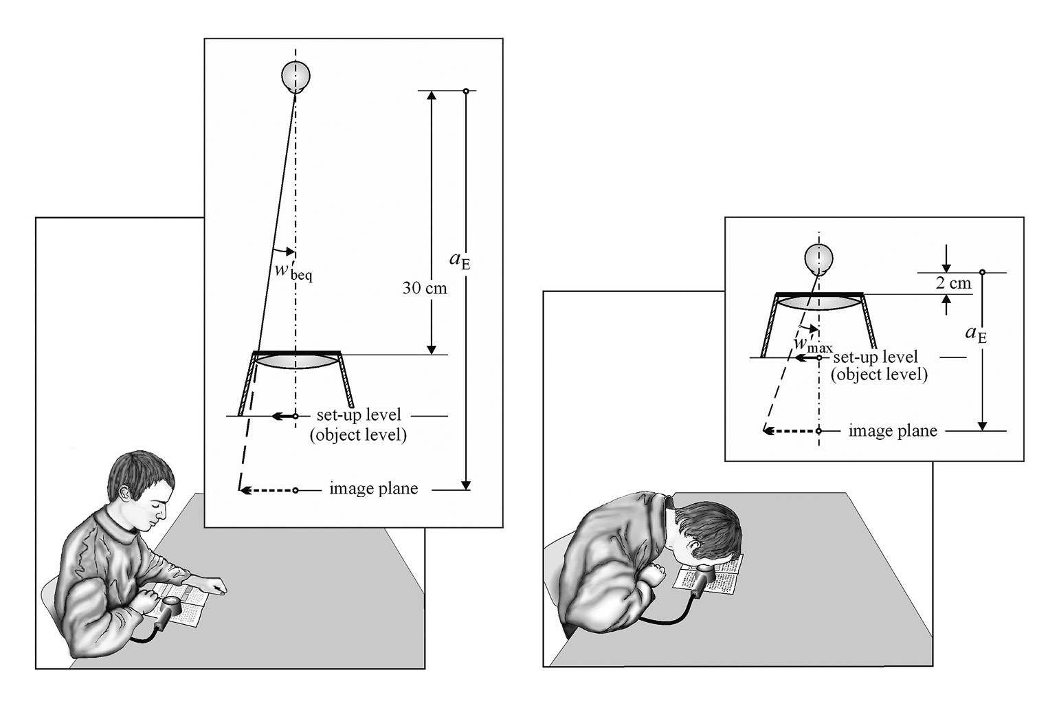
• Comfortable sitting position: If the magnifier is used at a table with a normal head and body posture, the so-called “comfortable magnification” Γ‘beq applies. The distance between the eye and the table is then approximately 35 cm, so that in this situation a distance between the magnifier and the eye (e) of 30 cm can be assumed.
• Maximum proximity (i. e. minimum distance): If a patient moves as close as possible to the magnifier, they will achieve the “maximum magnification” Γ‘max . It is not possible to move closer than approximately 2 cm to the magnifier, so a distance between the magnifier and the eye (e) of 2 cm is assumed for this situation.
Figure 2 illustrates the two borderline situations. It can be seen that the angle w’ at which the eye sees the magnified image increases from w’beq to w’max as the eye approaches the magnifier. The magnification then increases from Γ’beq to Γ’max.
When the eye moves closer to the magnifier, not only does the magnification increase, but so does the accommodation requirement or the necessary near addition, as the adjustment point aE shortens. The reciprocal of aE gives the amount of accommodation required, provided that emmetropia is present. For older patients without significant accommodation range, this value corresponds to the necessary near addition Z of suitable glasses. The following applies:
Z = 1 / (−aE)(8)
and with
aE = s‘ − e(9)
the following then applies
Z = 1 / (e − s‘) (10)
The near addition Z is therefore – just like the magnification Γ’ – a function of e and can also be represented graphically within the above-mentioned limits. For a comfortable sitting position, which results in Γ’beq – Zbeq is reqired, and for maximum closeness to the stand magnifier, which results in Γ’max – Zmax is required.
Materials and methods
Magnifying glasses
The study examined 31 magnifying glasses from the companies “Eschenbach Optik GmbH” and “A. Schweizer GmbH.” The product series “varioPlus,” “scribolux,” “visolux+,” and “powerlux” are available from Eschenbach. The Schweizer product series “Modular LED,” “Ökolux plus,” “Ergo-Lux MP,” and “Twin-Lux MP” are included in the study. All models from the respective delivery ranges with refractive indices between D = 6 D and D = 28 D were included. Note: Some magnifiers with even higher refractive indices (e. g., 39 D) are available in the product ranges, but these are excluded because their diameters are so small that no significant field of view diameter can be achieved at a “comfortable” distance. Due to the field of view, these magnifiers can only be used effectively at close range, so that it is not useful to determine and specify a comfortable magnification here.
The stand magnifiers used are listed in Table 1 with their item numbers. For magnifiers that are available in different light colors, the item number corresponds to the version with a color temperature of 4500 K (Schweizer) or 3000 K (Eschenbach).
Determination of magnification range and near addition
As formulas 7 and 10 show, the magnification achieved and the necessary near reading addition can be calculated for each magnifier-eye distance (e) if the magnification scale β‘ and the image focal length s’ are known.
The magnification scale β‘ and the image focal length s’ were determined on the optical bench using an analog SLR camera (Praktica TL 1000). This was used because a split-image indicator is integrated into the viewfinder as a focusing aid. The camera had a lens (Praktica T 2.8/50) with a fixed focal length and manual focusing. The focus was adjusted using the viewfinder image. Three measurements were always taken by one person and averaged. An internal microprism grid ring in the center of the viewfinder (middle circle) was used to fine-tune the adjustments (showing a “flicker” in the image field when out of focus).
The central circle represents a split-image indicator. This indicates an out-of-focus setting by showing an offset in the center of a vertical edge in the center of the image. However, the focus is not adjusted by turning the lens, but by changing the distance of the camera, which is set to a fixed close-up distance.
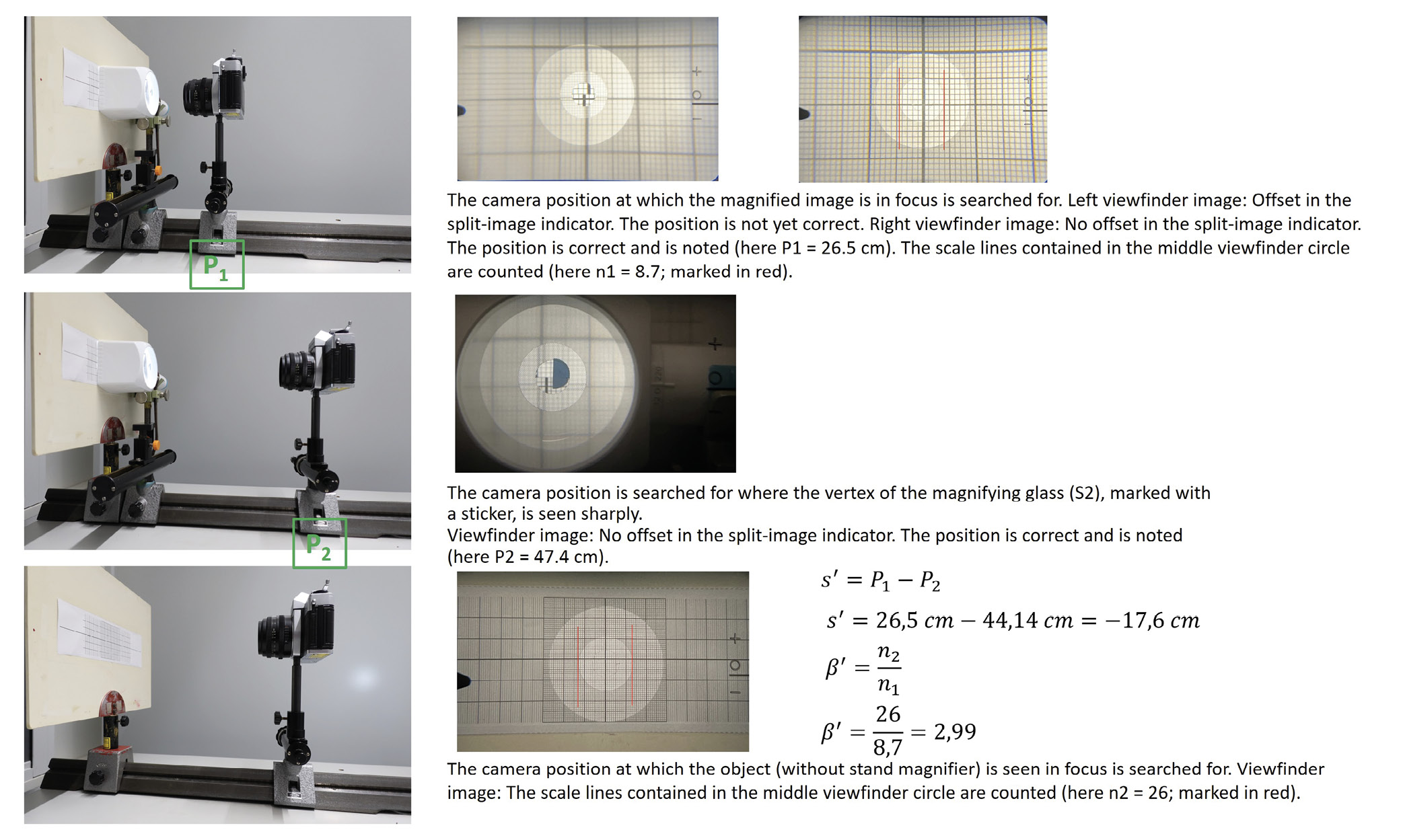
Figure 3 shows the measurement setup. The stand magnifier was placed flat on a solid base (= mounting surface) covered with graph paper. The SLR camera was mounted on a sliding mount at a variable distance from the magnifying glass. The position of the slide could then be read on the optical bench. The camera lens was set to a fixed near distance, ideally 35 cm. Both the stand magnifier and the camera could be moved vertically and horizontally using the holding devices and slide designs, enabling precise alignment. For centration, the camera and magnifier were brought as close together as possible and aligned subjectively with each other so that the apexes and thus the optical axes were aligned.
At the start of the measurement, the camera was moved closer to the magnifier until a sharp image of the graph paper (= magnifier image) was seen in the camera’s viewfinder. This was achieved when a vertical line on the graph paper, which run through the center of the viewfinder, showed no offset in the cross-sectional image indicator. (Note: For some of the stand magnifiers examined, the distance set on the camera lens had to be increased to 45 cm or 55 cm, as these magnifiers produced relatively distant magnifier images.) The “sharp” position of the camera on the optical bench (= P1) was noted and the number of scale lines in the center of the viewfinder circle was counted and recorded (= n1).
Next, the front surface of the magnifier was marked centrally with a sticker, the vertical edge of which was located at the apex S2 of the magnifier. The camera was then moved away from the magnifier until the sticker was in focus in the viewfinder and the edge of the sticker passed through the intersection indicator without any offset. The camera position on the optical bench (= P2) was noted. The displacement of the camera from P1 to P2 corresponded in amount to the image focal length s’.
Finally, the stand magnifier was removed and the camera position was sought at which the graph paper (= object) was seen sharply and without offset in the split-image indicator through the camera viewfinder. In this position, the scale lines (= n2) were counted again. The position of the camera was not relevant for later calculations. However, it was critical that the three settings or measurements were made with the same distance setting on the lens.
The magnification scale β‘ was calculated from the quotient of the number of scale marks n2 (setting for the object) and the number of scale marks n1 (setting for the magnifying glass image).
β‘= n2 / n1(11)
The image focal length s’ is determined by calculating the difference between the camera position P1 (focus on the magnifying glass image) and the camera position P2 (focus on the apex S2).
s‘ = P1 − P2(12)
Figure 3 contains a numerical example illustrating this.
If the calculated image focal length s’ and the determined magnification scale β‘ are inserted into Formula 7, the magnification Γ‘ can be determined for any magnifier – eye distance e.
Similarly, inserting the calculated image focal length s‘ into Formula 10 yields the required near addition Z for any magnifier – eye distance e.
Results
Table 1 shows the results for both the magnification (Γ‘) and the necessary near addition (Z) for all of the magnifying glasses examined here for both limit distances (comfortable use and maximum approximation).
The underlying calculations are shown here as an example for the Schweizer Optik Ökolux plus 16 D stand magnifier.
For the magnifier mentioned, an image focal length s’ = −15.9 cm and an magnification scale β‘ = 3.19 were determined (see Table 1).
• Calculation of the “comfortable magnification” using Formula 7
Γ‘beq = 3,19 × (−25 cm) / (−15,90 cm − 30 cm) = 1,74
• Calculation of the “comfortable near addition” using Formula 10
Zbeq = 1 / (0,30 m − (−0,1590 m)) = 2,18 D
• Calculation of the “maximum magnification” using Formula 7
Γ‘max = 3,19 × (−25 cm) / (−15,90 cm − 2 cm) = 4,45
• Calculation of the “maximum near addition” using Formula 10
Zmax = 1 / (0,02 m − (−0,1590 m)) = 5,59 D
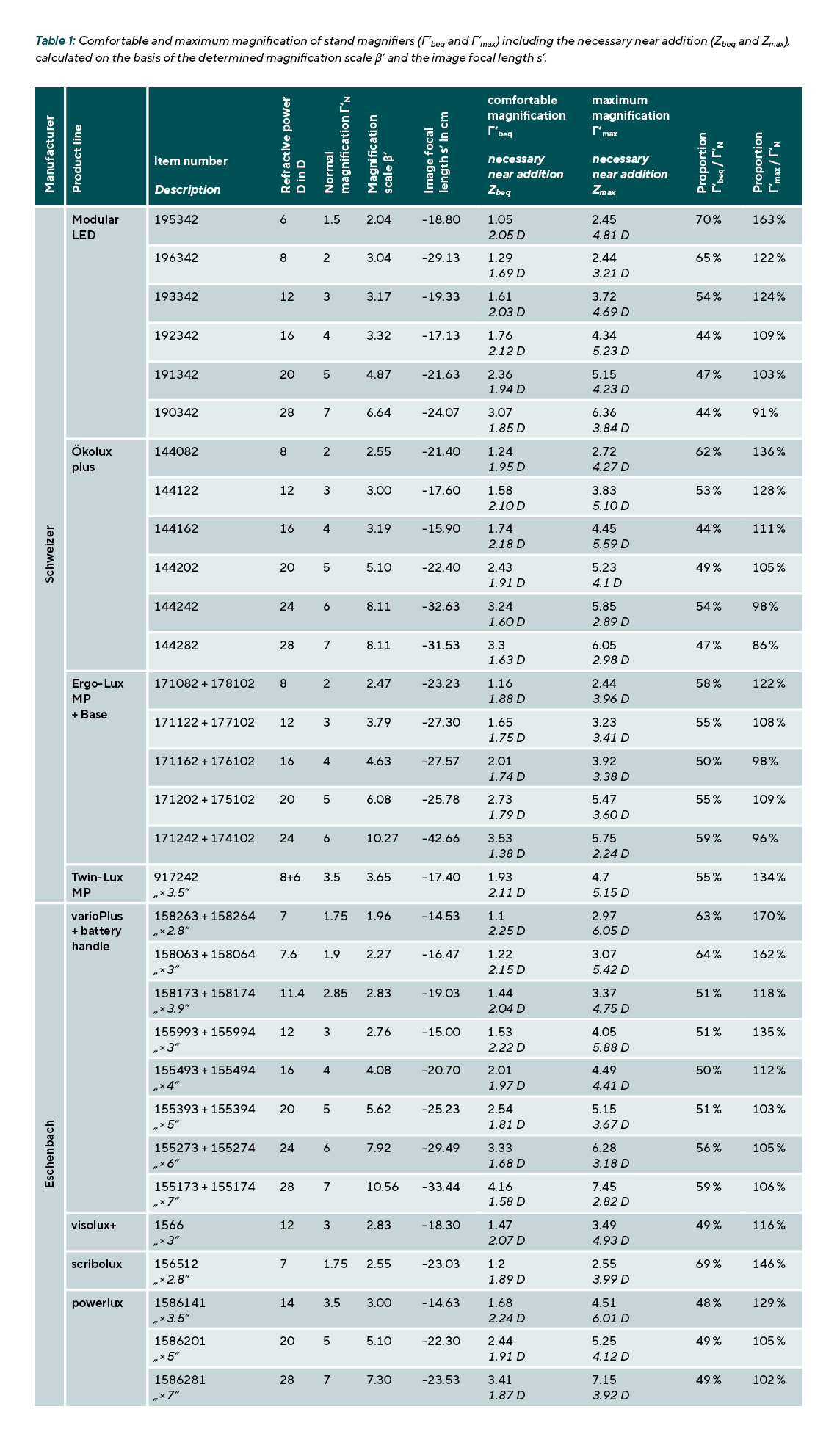
As Table 1 shows, “comfortable” use of the stand magnifiers examined achieved magnifications of between 44 % and 70 % of normal magnification. In approximately one third of cases, namely 10 out of 31 magnifiers, the magnifications were reduced to less than 50 % of normal magnification.
The remaining 21 stand magnifiers achieved magnifications between 50 % and 70 % of normal magnification.
Since the magnified image was relatively far from the eye during comfortable use (distance aE is relatively large in terms of magnitude), only relatively low near additions would be necessary in these situations. For 18 of the 31 stand magnifiers (= 58 %), the necessary near addition would be less than +2.00 D.
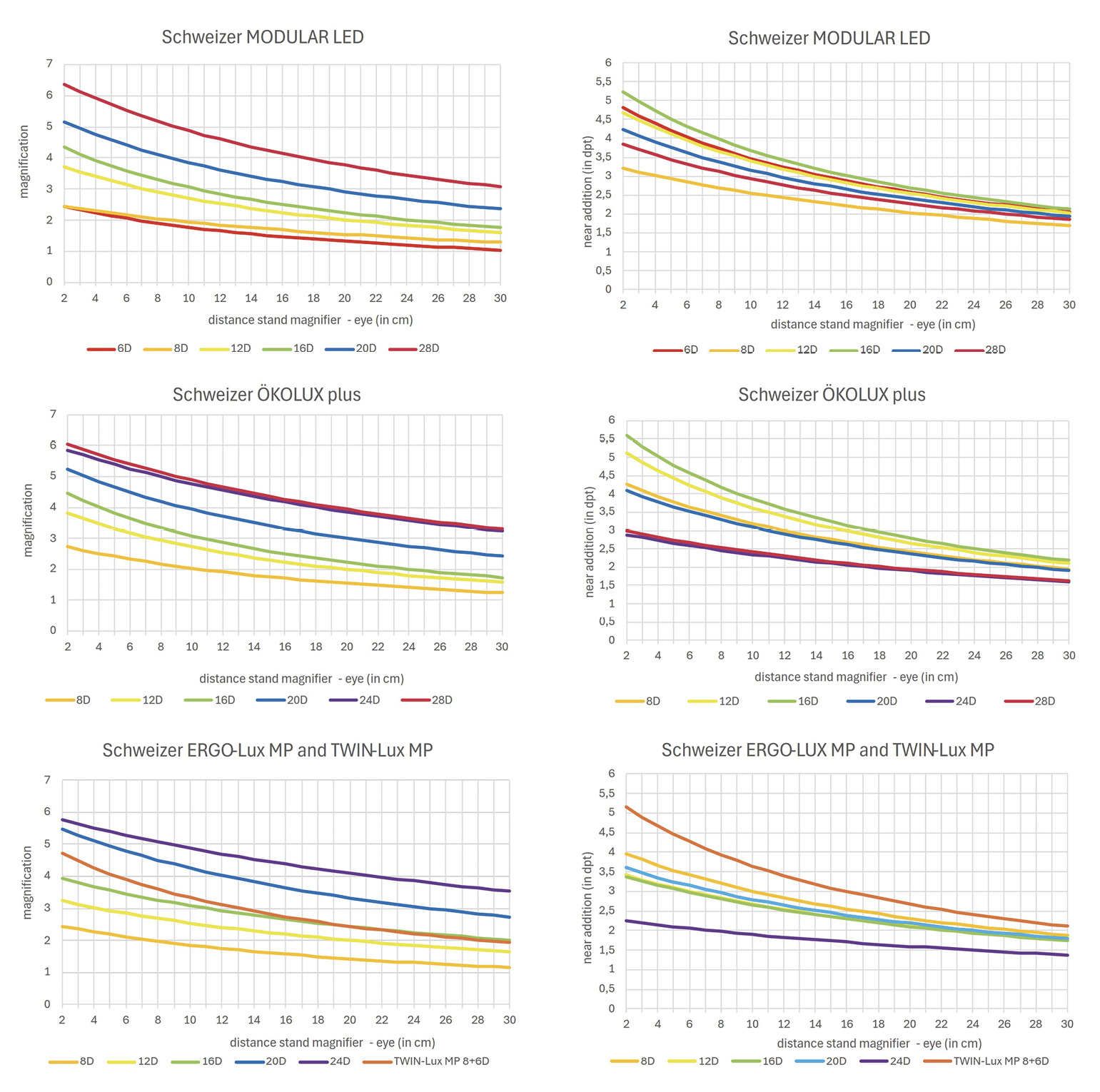
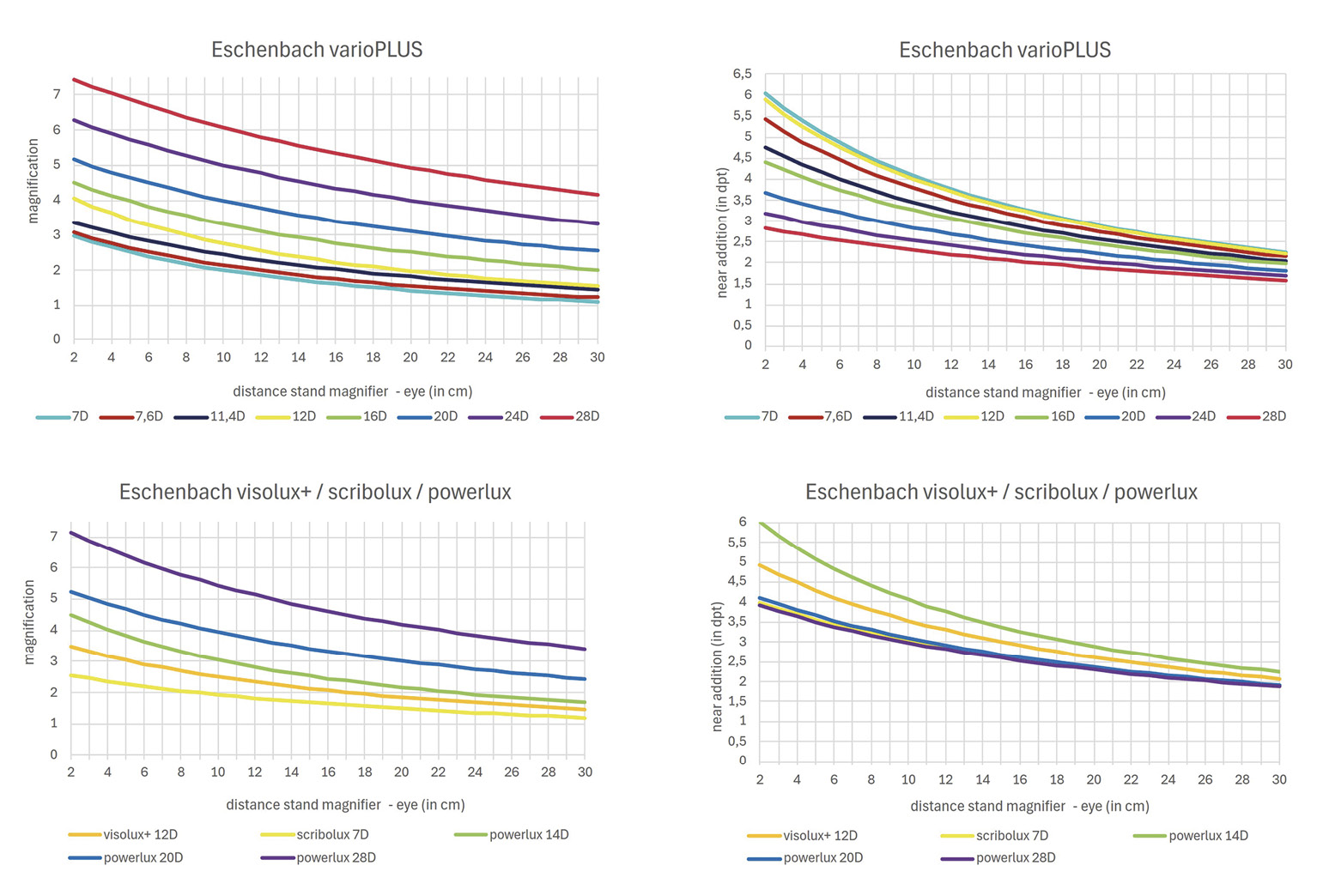
Figures 4 and 5 show the magnifications achieved (Γ‘) and the necessary near additions (Z) for all stand magnifiers examined as a function of the distance between the stand magnifier and the eye (e) over a distance range from e = 2 cm (maxima approximation) to e = 30 cm (comfortable sitting position). Bringing the magnifier closer increased the magnification significantly. The increase can be seen for all stand magnifiers in the diagrams in Figure 4 (Schweizer) and Figure 5 (Eschenbach). The shorter the image focal length (s’), the steeper the increase, meaning that users benefit more in terms of magnification when the magnifier is brought closer. At maximum proximity (e = 2 cm), the magnification is at least 75 % of the normal magnification (Γ’N). For the majority of the stand magnifiers (n = 25 out of 31; 81 %)), magnifications higher than Γ’N were achieved.
Just as the magnification increases with shorter distances, the necessary near addition also increases. See the diagrams on the right-hand side of Figure 4 (Schweizer) and Figure 5 (Eschenbach). For 23 of the 31 magnifying glasses, the near addition (Zmax) must be more than 3.5 D, with the highest value being Zmax = 6.05 D.
Discussion
The results in Table 1 show that when the stand magnifier is used “comfortably,” the magnifications achieved (Γ’beq) are significantly lower than the calculated normal magnification and often only reach about 50 % of this value. The actual magnifications are even further removed from the so-called “commercial magnification” (Γ’Hand = Γ’N + 1), which is sometimes specified in catalogs for some low-power magnifiers. For example, the Eschenbach varioPlus stand magnifier with a refractive power of 11 D is specified in the catalog as having a magnification of 3.9 (= commercial magnification). However, the comfortable magnification (Γ’beq) determined here is only 1.44. That is 37 % of the magnification stated in the manufacturer’s product catalogue.
As one moves closer to the stand magnifier, the magnification always increases. The maximum magnification (Γ’max) achieved at a distance of 2 cm between the magnifier and the eye is approximately the same as the normal magnification for most stand magnifiers. Since not only the magnification but also the diameter of the field of view increase when reducing the eye’s distance to the magnifier, low vision care should encourage patients to move closer to the magnifier whenever possible.
Experience has shown that this approach can be problematic and/or unfamiliar for many visually impaired people, who are frequently of advanced age, with ergonomic reasons being a key issue, leading to rejection of such recommendations. In some cases, however, it is possible to reduce the working distance at least partially, for example by using a low chair and/or a fixed, raised surface on the table (e. g., a reading desk).
When testing the stand magnifier in clinical practice, it is advisable to use a trial frame with a suitable addition. If the person viewing is at a comfortable working distance, near additions of 1.5 to 2 D are usually suitable. Existing “normal” reading glasses are often too strong in terms of near addition and can cause blurred vision (“fogging”). If, on the other hand, the working distance can be significantly reduced in order to achieve the highest possible magnification and a large field of vision, normal reading glasses may prove to be too weak.
For best possible, i. e. maximum near acuity (or minimum distance?), near additions of up to 6 D may be required. In practice, the optimum near addition can be determined relatively easily with a trial frame. (Note: At maximum near, stand magnifiers can only be used monocularly. A near addition is then tested/adjusted for the better “reading eye.”)
In clinical low vision practice, it would be helpful if manufacturers of stand magnifiers would specify the “comfortable” and “maximum” magnification (Γ’max and Γ’beq) as well as the ‘comfortable’ and “maximum” near addition (Zbeq and Zmax) in their product catalogues. With this information, it would be possible to estimate the suitability of a stand magnifier for a given magnification requirement.
An even more effective prediction, also for other distances, would be possible if the manufacturer specified the magnification scale (β‘) and the image focal length (s’) for each stand magnifier in the catalogue specification. This would allow the magnification Γ’ and the required near addition Z to be calculated for any distance between the magnifier and the eye (e) with little effort (formulas 7 and 10). Similarly, it would be helpful for low vision specialists if the manufacturer provided or published a diagram for each magnifier (in a catalog or on a website) showing the magnification and the necessary near addition as a function of the distance between the magnifier and the eye, as shown in the diagrams in Figures 4 and 5. In this way, the exact values for Γ’ and Z could be determined relatively easily in the test situation for people who only approach the magnifier to a limited extent (for example, up to a distance of 20 cm between the magnifier and the eye).
Figures 4 and 5 also show that the “ranking” of magnifiers in terms of magnification is not identical to that of the near addition. This means that a magnifier with low magnification does not automatically require a low near addition.
Despite repeated measurements and averaging, it is possible that measurement errors have occurred in this study, for example for the magnification scale β‘ and the image focal length s’. The effect on magnification and on the necessary near addition depends largely on the respective stand magnifier and the distance between the magnifier and the eye. The error estimate is shown here as an example for the “Schweizer Optik Ökolux plus 16 D” stand magnifier (see sample calculation in the results section): To determine the magnification scale (β‘), a reading accuracy of half a scale mark can be assumed for the number of scale marks in the middle viewfinder circle (n2 and n1) of half a scale division. With a maximum error estimate (β’max = n2,max / n1,min), this would result in β‘ = 3.46 (instead of 3.19)
To determine the image focal length (s’), which results from the two camera positions, a measurement error of 5 mm can be assumed. A focal length that is 5 mm shorter would be s’ = −15.4 cm in this example.
If the calculations documented in the results section are performed using these values, the results are Γ‘beq = 1.91 (instead of 1.74) and Γ‘max = 4.98 (instead of 4.45). The deviations for the magnification are therefore approximately 10 % and 12 % respectively in this unfavorable combination of errors. For the near addition results, based on the shorter calculated image focal length, Zbeq = 2.20 D (instead of 2.18 D) and Zmax = 5.75 D (instead of 5.59 D) are determined to be too short. These differences are very small and can be neglected.
Conclusion
Due to their positive characteristics (good image quality, easy handling, steady image, fixed image distance, often integrated bright lighting), stand magnifiers are important for visually impaired people for reading. Some of the devices are also suitable for short-term writing or handling of objects.
However, the magnification specifications on the magnifier or in the catalogue, which are usually based on the assumption that the magnifier achieves normal magnification or even commercial magnification, are not accurate when the magnifier is used “comfortably.” The magnification achieved during comfortable use is significantly lower, often only about half the normal magnification. Only when the magnifier is used very close to the eye can magnifications be achieved that correspond to normal magnification or are even higher. For ergonomic reasons, it is likely that only in exceptional cases will older visually impaired people be able to achieve the maximum magnification by using the magnifier very close to their eyes.
The targeted adjustment of a stand magnifier would be simplified if low vision specialists had access to additional data on the stand magnifiers. This would also make it easier to prescribe the appropriate reading glasses.
Conflict of interest
The authors have no conflict of interest with regard to the methods and devices mentioned in the article
COE Multiple Choice Questionnaire
The publication "Magnifications of stand magnifiers" has been approved as a COE continuing education article by the German Quality Association for Optometric Services (GOL). The deadline to answer the questions is 1st May 2027. Only one answer per question is correct. Successful completion requires answering four of the six questions.
You can take the continuing education exam while logged in.
Users who are not yet logged in can register for ocl-online free of charge here.