Lens Checking: How Eye Care Practitioners Verify and Inspect Rigid Contact Lenses
Purpose: The primary focus of this article is to explore the critical aspects of verifying and inspecting RGP contact lens parameters in clinical practice. The verification process is essential to ensure that patients receive lenses with accurate and optimal parameters, thus improving their visual experience and comfort. The article delves into the methods and instruments available to eye care practitioners for verifying key parameters, including back surface radii, total lens diameter, lens power, lens thickness, blends, and surface quality.
Material and Methods: The discussion centers on the techniques and tools employed in the verification and inspection of RGP contact lens parameters. It emphasizes the significance of maintaining a clean and controlled environment for these assessments. Calibration and error minimization strategies are highlighted to enhance measurement accuracy. The article provides insights into device-specific measurements and the importance of averaging measurements to mitigate deviations.
Results: The article outlines various procedures for verifying the essential parameters of RGP contact lenses. It covers methods for checking back surface radii, including the use of radiuscopes, keratometers, and corneal topographers. Verification of lens diameter is detailed with V-shaped measuring gauges, measuring magnifiers, and projection magnifiers. Lens power verification is explored through lensmeters and specialized lensmeter calibration techniques. Finally, the measurement of lens thickness, the inspection of lens edges, and the evaluation of surface quality and blends between different lens zones are addressed.
Conclusion: This article underscores the significance of thorough verification and inspection of RGP contact lens parameters in clinical practice. These essential steps ensure that patients receive lenses that meet their specific needs, contributing to improved visual acuity, comfort, and overall ocular health. Eye care practitioners should check their patients’ RGP contact lenses according to the ordered parameters. By following the described methods and employing appropriate instruments, the fitting and prescribing of rigid gas-permeable contact lenses can be enhanced.
Introduction
The importance and benefits of rigid gas permeable lenses (RGP lenses) for quality of vision,1 ocular health,2–4 and a decreased rate of myopic progression,5 are well-established.
Nonetheless, between 2000 and 2010, interest in this lens option was steadily declining. The increasing popularity and variety of disposable soft contact lenses were proposed to put an end to the era of RGP lenses.6
Since 2010, however, a renewed interest in RGP contact lenses can be seen. This can be primarily attributed to new generations of orthokeratology lenses for myopia management and scleral lenses, whereas the market share of corneal RGP contact lenses remained relatively stable.7
In a longitudinal annual contact lens prescribing survey that was done among contact lens prescribers in 71 countries between 1996 and 2020, the amount of RGP contact lenses prescribed varied significantly across nations.8 In comparison to other countries, Japan, the Netherlands, and New Zealand were observed to have a consistently more significant percentage of RGP lens prescriptions.
In the year 2020, RGP contact lenses constituted 11.8 % of the total contact lens prescriptions among the 71 nations included in the survey, exhibiting considerable variation. In the Netherlands, approximately 37 % of prescribed contact lenses were of this type, whereas in New Zealand and Spain, the corresponding figures were 27 % and 23 %, respectively, during the same year. These figures were much lower in the USA and Great Britain, at about 9 % and 5 %, respectively. This survey did not include data from Germany. However, a separate report for the first quarter of 2020 from the German optical industry stated that its market share of RGP lenses was 4.2 % of all contact lenses.9
From an ocular health perspective, RGP lenses may be the preferred choice of all types of contact lenses. A prospective, randomized, double-masked, clinical trial showed that wearing hyper-oxygen transmissible RGP lenses did not result in an increased Pseudomonas aeruginosa binding to exfoliated corneal epithelial surface cells, whereas this was the case with both hydrogel lenses and silicone hydrogel lenses.10
A new generation of scleral and mini-scleral RGP lenses provides excellent corneal oxygen supply and comfort and is now additionally used for managing dry eye conditions.11 In addition, orthokeratology requires the use of reverse geometry RGP lenses, which has been gaining popularity in recent years.12
RGP lenses are the first choice for compromised corneas, such as in keratoconus,13 pellucid marginal degeneration,14 keratoglobus and Terrien’s marginal degeneration,15 keratectasia after refractive surgery,16 as well as high and/or irregular astigmatism.17
Before being dispensed to patients, RGP lenses should have their parameters verified and inspected. There are many reasons why a patient‘s vision and their experience can be impacted, such as a lens with one or more incorrect parameters, or the lenses being switched in the storage container or the eyes. If the parameters of the left and right lenses differ, this can affect the patient’s vision, the lens fit, and comfort. If a lens modification was performed, for instance, a change in lens power, the new parameters need to be verified and recorded. Used lenses may be warped, scratched, or have chipped edges, which can compromise comfort, visual acuity, contrast sensitivity, and corneal integrity.
This article focuses on verification techniques for RGP contact lens parameters that are recommended in clinical practice.
Tolerances for Rigid Contact Lens Parameters
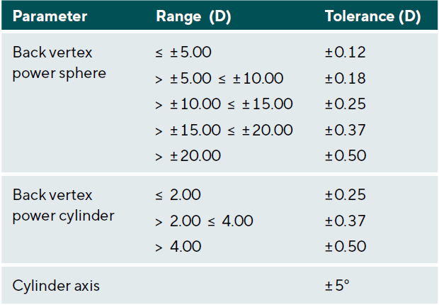
The successful fitting of rigid contact lenses requires that the parameters of these lenses fall within certain tolerance ranges, as defined by the International Organization for Standardization (ISO).18 ISO Standard 18369-2:2017 is titled ”Ophthalmic Optics – Contact Lenses – Part 2” and lists the tolerances for dimensional and optical parameters in addition to the physical, chemical, and optical properties of rigid contact lenses. Some of the dimensional and the optical parameters can be easily verified in clinical practice. These are presented in Tables 1 and 2. Their tolerances should be used as guidance on whether RGP contact lenses can be dispensed or whether they need to be replaced.
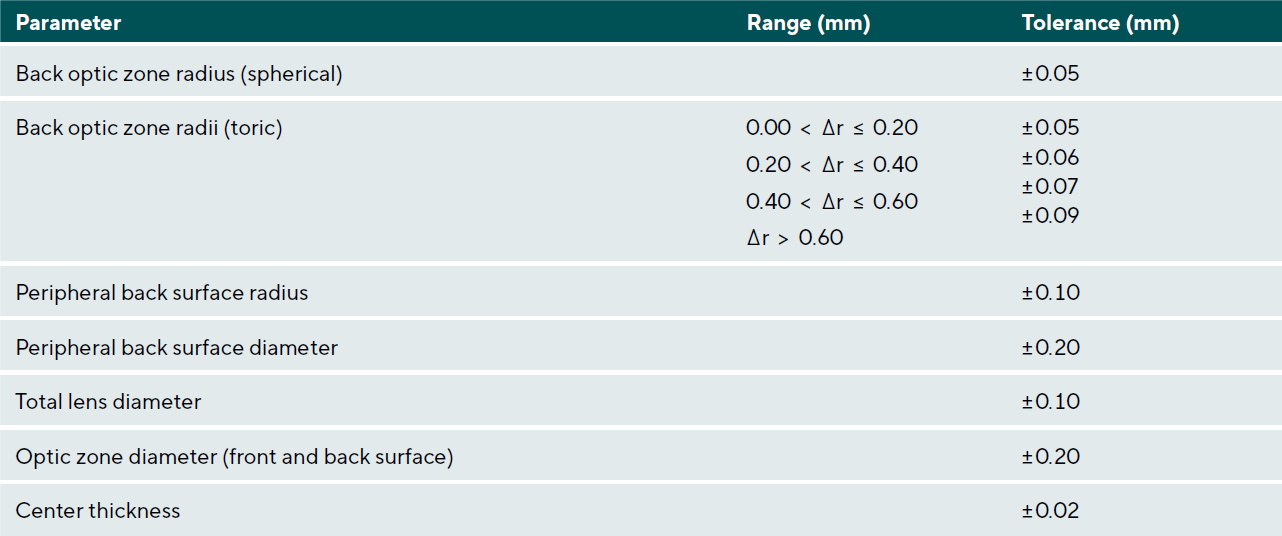
A note should be made regarding the central back optic zone radius. The specified tolerance of ± 0.05 mm officially applies to rigid, high gas-permeable contact lenses used in orthokeratology as well. However, in this procedure, even a small change in sagittal depth of 5 μm can have a clinically significant impact on the treatment effect. Therefore, authors Chiu and Cho suggested using a tolerance value of ± 0.02 mm for the central back optic zone radius of orthokeratology lenses. This adjustment accounts for the specific requirements of orthokeratology lens fitting.19,20
Verification and Inspection of RGP Contact Lens Parameters
The number of parameters that can be verified in clinical practice will depend on the equipment available. It is important to consider the capabilities and limitations of the equipment when verifying contact lens parameters in a clinical setting. Some of these parameters are quick and straightforward to verify, while others require specialized equipment and are often associated with a significant amount of time and effort. Individual lens parameters such as surface radii, diameters, and thickness can be measured with different devices, although the measurement accuracy can vary at times.
At the minimum, eyecare practitioners should verify back vertex power, back optic zone radius, total lens diameter, and center thickness. In addition, lens edge, surface quality, and blends between different lens zones should be inspected.
Preparatory Measures
The verification of RGP contact lens parameters should take place in a clean and undisturbed environment. Cleaning and storage solutions, as well as a contact lens case, should be readily available. A lint-free, soft cloth is recommended for drying the lenses. Additionally, for some measurements, a physiological saline solution (0.9 % sodium chloride) may be necessary. The measuring instruments used should be calibrated according to the manufacturer‘s specifications.
Calibration and Minimization of Measurement Errors
A clinical measurement can represent the currently existing parameter, but it can also deviate from it. These deviations are, on the one hand, specific to the device used, and on the other hand, they depend on the individuals conducting the measurements. In practice, it is important to identify these measurement errors and minimize them as much as possible.
Device-specific measurement errors can be limited through regular calibration. It is important to follow the manufacturer‘s protocols in this regard. Some clinical instruments are known to exhibit significant variation in sequentially conducted measurements.19,20
If this variation cannot be reduced through calibration, the mean of a series of subsequent measurements should be used. To determine how many of these measurements are required for adequate averaging, their standard deviation must be known. This can be found through a series of measurements. Assuming the manufacturing tolerances listed in Tables 1 and 2, the required number of repeated measurements to form a robust mean can be determined using the following equation:
n = (SDM / SEP)2
In this equation, n is the number of measurements, SDM is the standard deviation of repeated measurements, and SEP is the standard error of the respective contact lens parameter, which corresponds to its manufacturing tolerance.
From this equation, it is evident that a small manufacturing tolerance in combination with a high standard deviation requires a large number of measurements for averaging. This is particularly important to consider when verifying back surface radii in orthokeratology lenses.
Preparation of Contact Lenses
Before checking their manufacturing parameters, rigid contact lenses should be manually cleaned and dried with a lint-free, soft cloth. Regarding the storage of lenses before inspecting their parameters, the literature provides conflicting recommendations. Some authors advocate moist storage for at least 12 hours to maintain parameter stability, while others recommend dry storage.21,22
These statements are based on older studies that examined low gas-permeable materials from previous generations. In 2014, a study was conducted with medium gas-permeable (Boston ES) and high gas-permeable (Boston XO) contact lenses. According to its findings, moist storage of these contact lenses was not necessary for maintaining their parameter stability, although 30 minutes equilibration in saline is suggested.18,23
Verification of Surface Radii
Back optic zone radius (BOZR), back peripheral zone radii, and front surface radius can be measured for verification.
The BOZR is a very important parameter to verify in an RGP contact lens since it affects the lens-to-cornea fitting relationship. In conjunction with the lens diameter and the peripheral curve system, an unsuitable BOZR can lead to a reduction in visual performance, comfort, tear exchange, and inadequate or excessive movement of the contact lens. In the case of orthokeratology lenses, a deviation in the BOZR can result in unintentional over-treatment or under-treatment of refractive errors.
In the following section, we will review several clinical instruments that are available for the verification of the surface radii of RGP contact lenses.
Radiuscope (optical micro-spherometer)
The standard instrument used to measure the BOZR is the optical micro-spherometer, which is more commonly referred to as a radiuscope or a radius gauge. The optical concept behind a radiuscope is known as Drysdale’s principle.24 The refractive index of the contact lens material does not influence the radius measurement because it is based on mirror optics.
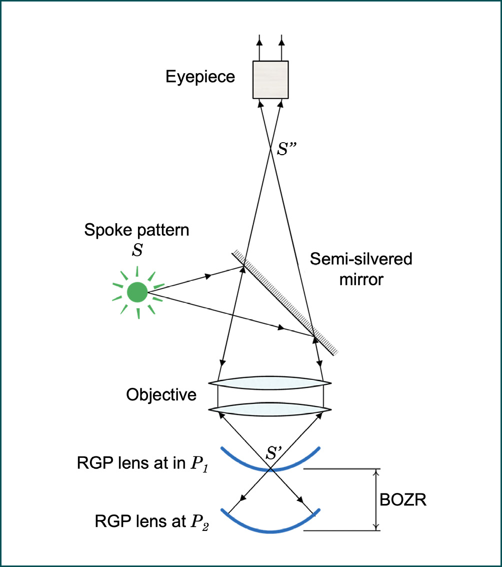
A radiuscope’s basic arrangement for measuring the BOZR of an RGP contact lens is illustrated in Figure 1. Light from an illuminated spoke-pattern target (S ) is focused on point P1, where a real image of the spoke pattern (S’ ) is created. A microscope is focused on the same point. When a smooth RGP contact lens surface is aligned with point P1, the light is reflected through the microscope and a secondary clear image of the spoke-pattern (S’’ ) can be observed through the radiuscope’s eyepiece. Another clear image can be observed when the RGP contact lens is aligned at point P2. In this situation, the center of curvature of the contact lens back surface coincides with point P1. All light rays now strike the surface at 90-degree angles and are reflected back along their incident directions. An aerial image is then formed at P1 which can be observed with the microscope. The distance between points P1 and P2 is the BOZR of the contact lens. It equals the travel distance of the RGP contact lens, necessary to observe the two clear images. Although rarely used in clinical practice, the radiuscope can also be used to measure the convex front surface radius of a contact lens.
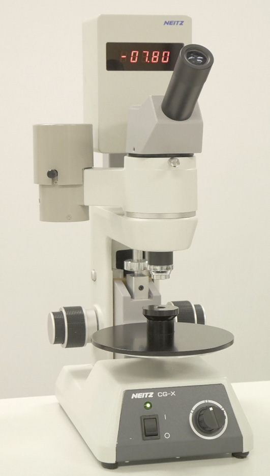
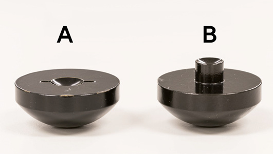
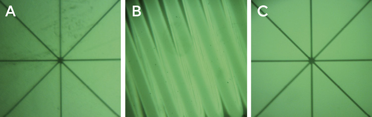
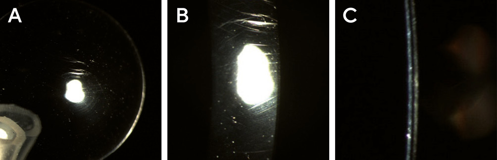
A typical radiuscope in measurement mode is shown in Figure 2. The contact lens to be measured is placed in a special lens mount. Different height lens mounts are used for measurements of the front and back surfaces to ensure proper positioning of the contact lens in the beam path of the radiuscope. These are shown in Figure 3. Before the measurement begins, the contact lens is first cleaned and dried. It is then placed on the lens mount, with the area to be measured facing the microscope, and the other surface is optically neutralized with a drop of saline solution. The distance of the contact lens relative to the microscope can be adjusted using a dial. Once the real image, usually in the form of a spoke pattern (Figure 4A) is focused at point P1 (Figure 1), the instrument‘s measuring scale is set to zero. While the contact lens is moved towards point P2 (Figure 1), an image of the device’s internal lamp filament (Figure 4B) can be observed. This indicates that the lens movement is in the correct direction. Once a clear spoke pattern image is recognized at point P2 (Figure 1), the measurement is complete, and the surface radius can be read from the measuring scale.
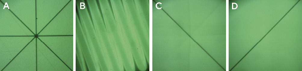
In the presence of a toric lens surface, the entire spoke-pattern image is clearly visible when the lens surface is positioned at point P1; however, only one of the spoke lines of the aerial image can be focused (Figure 5C) when the lens is positioned at point P2. This line image is created by one of the surface’s two principal meridians. To verify the perpendicular meridian, the location of P2 is changed slightly until the perpendicularly-located spoke line is in focus. The difference between these two positions equals the difference between the two BOZRs of the toric lens surface.
The peripheral radii of an RGP contact lens back surface may be confirmed by tilting the lens so that its peripheral surface is perpendicular to the illumination- and observation pathways. To obtain a clear spoke pattern image, the zone under investigation should be at least 1 mm wide.29 Although challenging to obtain, this measurement is crucial for validating mid-peripheral back surface radii in orthokeratology lenses, where these radii form a critically important zone that is intended to align with the wearer’s mid-peripheral cornea. This measurement is shown in Figure 6.
Since operating the radiuscope is a manual procedure, it is recommended to use the average of three subsequent readings in order to minimize the impact of measurement errors.26
Although the radiuscope belongs to the standard methods to determine the BOZR of rigid contact lenses, it is not available to every eye care practitioner.27 Therefore, other methods of BOZR verification, utilizing a keratometer or a corneal topographer, may be adopted.
Keratometer
In clinical practice, a keratometer can also be used to determine the BOZR of RGP lenses. Various attachments have been developed to hold the contact lens in place during the measurement procedure. Most commonly, the front surface of the RGP is held in a vertical position by the capillary force of a drop of saline within the concave depression of a lens holder that is attached to the keratometer’s headrest (Figure 7). Despite the slightly lower refractive index of saline, the front surface of the contact lens is essentially optically neutralized and the small discrepancy that exists is insignificant for the purposes of this verification procedure. Therefore, the observed images of the keratometer’s mires are reflected solely by the lens back surface. If the contact lens is held in a more stable horizontal position, the radius measurement can be obtained by using a 45° mirror or reflecting prism.25
The keratometer is designed to measure corneal front surfaces, which are convex surfaces. The approximate keratometer equation used for this purpose is:
r0 = 2Md
In this equation, r0 is the radius of curvature of the convex corneal front surface, M is the ratio of image size to object size of the keratometer mire, and d is the distance between the mire and its virtual image.
The equation assumes a constant distance d between the illuminated mire and its virtual image, created by the convex corneal front surface. This virtual image is behind the corneal front surface. When measuring a concave contact lens back surface, a real image of the mires is created in front of the surface. This difference results in a slightly incorrect radius measurement. For sufficiently accurate compensation, it is recommended to add a constant value of 0.03 mm to the determined measurement value for most types of keratometers.26
Depending on the type of keratometer, the detected radius of curvature represents an average over the central 2.5 mm to 3.0 mm. Therefore, the BOZR of a lens with a non-aspheric back optic zone can be assessed with reasonable accuracy; however, this is not the case for an aspheric contact lens, whose radii progressively increase from the center to the periphery of the lens.
The verification of the peripheral back surface radii of RGP lenses with a keratometer is also possible but typically requires a rotatable mirror system for positioning the contact lens and the measurement beam path.28
Corneal topographer
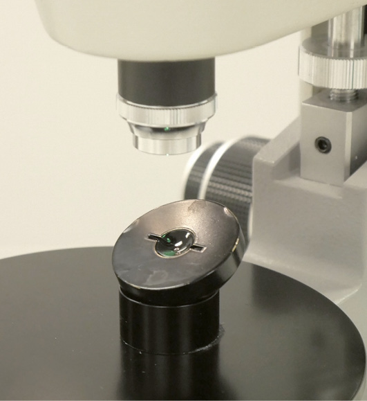
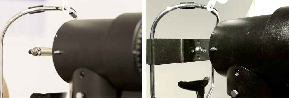
Similar to keratometers, corneal topographers can be utilized to determine the BOZR of RGP contact lenses. In this setup, a physiological saline solution optically neutralizes the contact lens front surface while positioning the lens back surface for measurement, necessitating the use of a lens holder. (Figure 8)
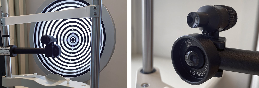
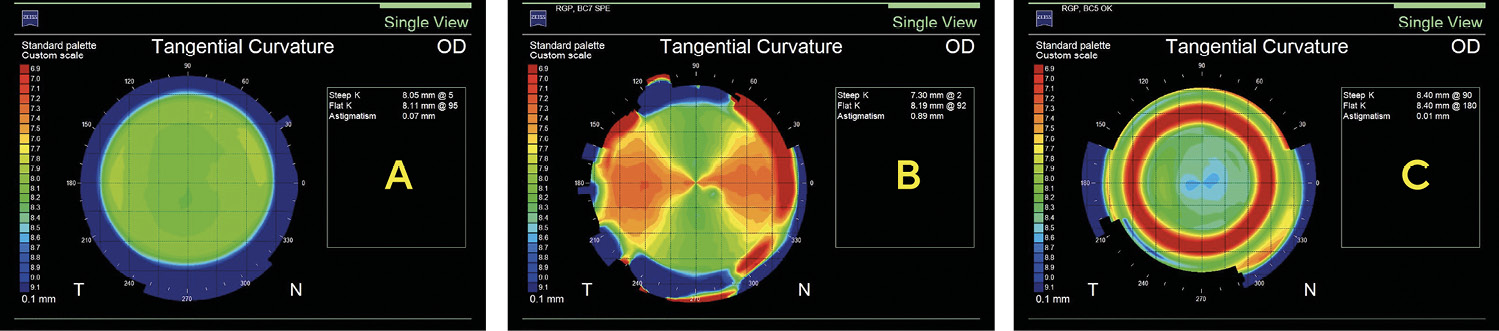
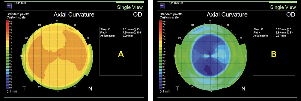
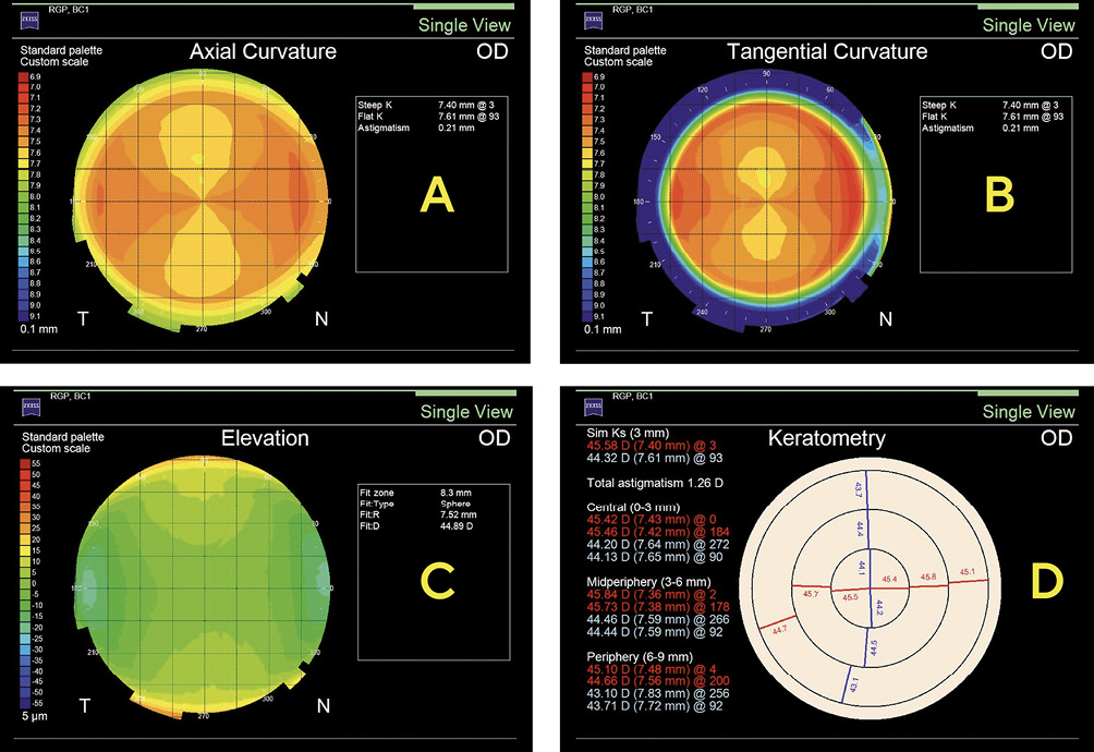
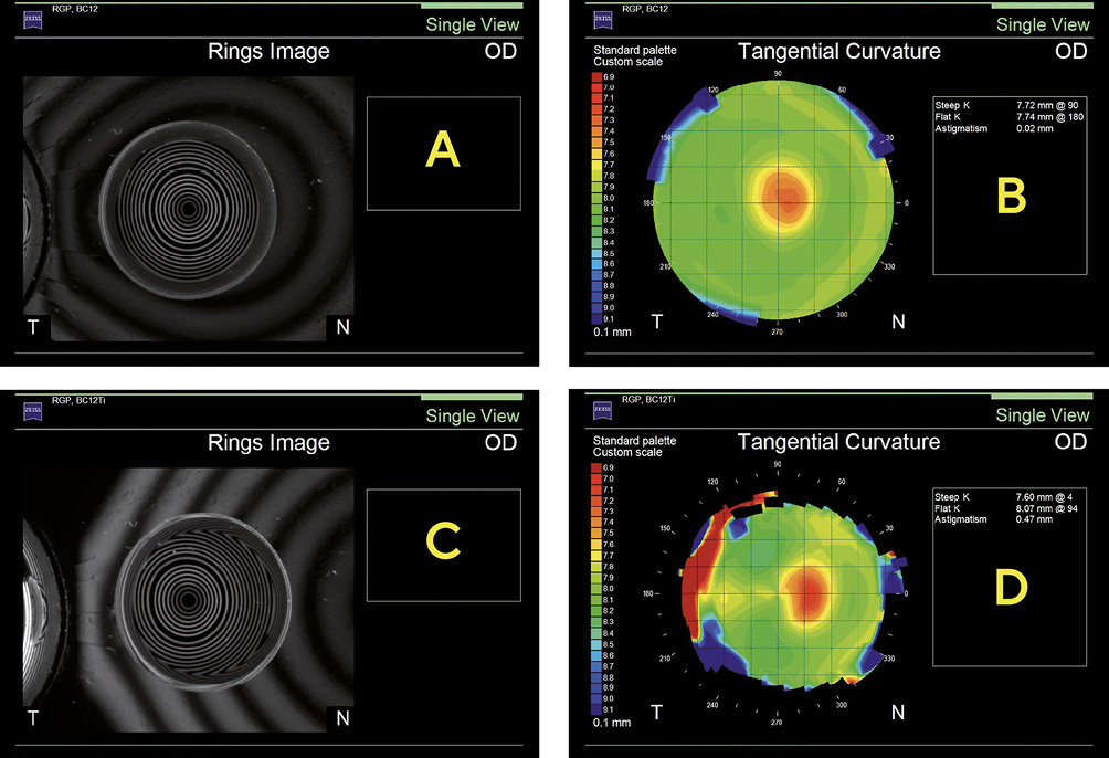
In this situation, the topographer’s illuminated Placido rings are reflected solely by the lens‘s back surface. Similar to a keratometer, a corneal topographer is designed to measure corneal front surfaces, which are convex surfaces. In its normal mode of operation, virtual images of the Placido rings are created behind the corneal front surface; however, when measuring a concave contact lens back surface, real images of the rings are created in front of the surface. This deviation can affect the detected sizes of the Placido ring images, and since the image size is a key component used to compute the surface radii, a slight deviation in the obtained values can result. Whether and to what extent this is the case, however, depends on the specific type of corneal topographer. The utilization of a corneal topographer is advantageous in determining the surface radii of contact lenses due to its ability to provide a high-quality topographic image. This is particularly true for RGP contact lenses that possess larger diameters, such as scleral lenses, as well as other specialized lenses that exhibit intricate back surface geometries, including toric lenses and orthokeratology lenses. The topographic assessment of various RGP contact lens back surfaces by a corneal topographer is demonstrated in Figure 9. The method also allows the identification of topographic surface irregularities and astigmatism due to lens warpage, which can be seen in Figure 10.
For visualization and analysis, a corneal topographer offers a variety of map types, such as the axial map, the tangential map, the elevation map, the keratometric map, and others. (Figure 11)
Additionally, it offers the advantage of efficient data storage organization within contact lens wearers‘ files, facilitating comprehensive record-keeping. In order to maintain the precision of the data acquired from the contact lens back surface, it is crucial to establish a proper alignment between its optical axis and the measurement axis of the topographer. The assurance of this is achieved through the careful observation of Placido ring reflex images and the subsequent readjustment of the contact lens holder to guarantee that the images are properly centered on the contact lens surface prior to capturing the image. In contrast to the radiuscope, the corneal topographer will capture an image in cases where the alignment is not adequately established. However, it is important to note that the obtained surface data may be inaccurate. This is especially important on aspheric contact lens surfaces, which is visualized in Figure 12.
Furthermore, not all corneal topographers are able to acquire images from concave surfaces. Eye care practitioners seeking to verify the surface radii of RGP contact lenses using corneal topographers should consult their topographer‘s manufacturer to confirm its suitability for measuring concave contact lens surfaces.
Verification of Diameters
The total diameter of rigid contact lenses typically ranges from 9.2 to 9.8 mm in most cases and is specified in increments of 0.1 mm. RGP contact lenses used for keratoconus and segmented bifocal contact lenses are often smaller (8.6 – 9.2 mm), while orthokeratology and scleral lenses have significantly larger diameters, typically ranging from 10.5 to 22.0 mm.29–31 In non-aspheric RGP lenses, a change in total lens diameter results in a change in the fitting pattern. Therefore, an accurate diameter assessment is important. It can be measured with a V-gauge, a measuring magnifier, or a projection magnifier.
V-shaped measuring gauge (V-gauge)
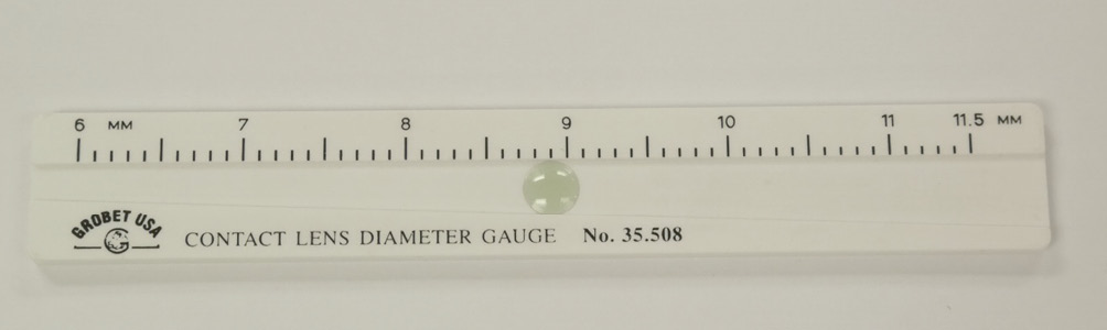
The V-shaped measuring gauge (V-gauge) is an inexpensive and simple instrument to measure the total diameter of an RGP contact lens. It contains a trapezoidal channel with widths increasing from 6.0 to 11.5 mm that is cut into plastic or metal. Depending on the manufacturer, the scale displays 0.1 or 0.2 mm increments. During measurement, the dry and clean RGP contact lens is placed concave side down into the channel at its widest edge. The V-gauge is then carefully tilted, allowing the lens to slide toward the narrow end until it stops. The diameter is read from the point where the opposite edges of the contact lens meet the scale. Figure 13 shows a V-gauge with an appropriately positioned contact lens. Despite its simplicity, the V-gauge gives accurate and reproducible readings of the total diameter of RGP lenses.32
Measuring magnifier (loupe)
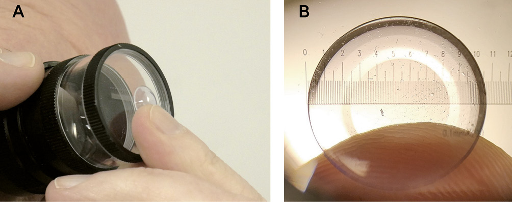
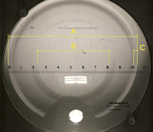
The measuring magnifier, or loupe, can be utilized for measuring total diameter, optic zone diameter, and peripheral zone widths. It consists of a baseplate with an engraved scale and an adjustable eyepiece with 7× or 10× magnification. The scale ranges from 0.0 to 20.0 mm in 0.1 mm increments. The RGP contact lens is placed on the baseplate, concave side down (Figure 14A), and held up to a background light source, which produces different levels of contrast when refracted by the different surface radii of adjacent lens zones (Figure 14B). Higher contrast between zones may be observed in lenses with a larger difference between radii of adjacent zones, while lower contrasts between zones of similar radii may be enhanced by changing the direction and/or intensity of the light source.
Projection magnifier
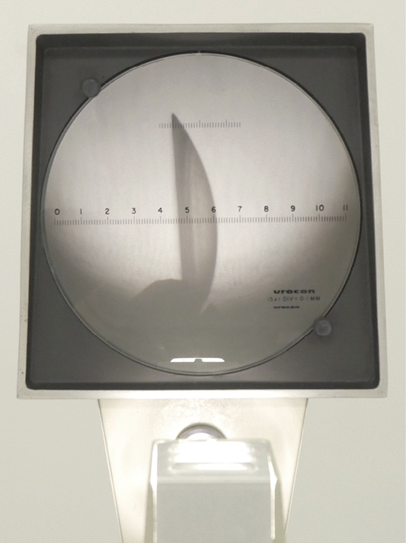
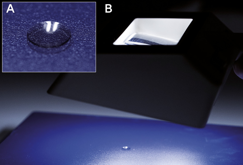
Much like the measuring magnifier, the projection magnifier can be used to measure total diameter, optic zone diameter, peripheral zone widths, surface quality, blend, and edge design. The dry and clean RGP contact lens is placed in a holder and illuminated by an internal lamp. A magnified image is projected onto a calibrated screen, which contains a scale. The various zones of the lens show up in different shades against the scale and can therefore be measured easily. An image of the projection magnifier with a lens in place is depicted in Figure 15.
Verification of Lens Power
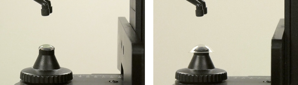
Front and back vertex power as well as optical quality can be measured with a lensmeter, which typically is brought into a vertical measuring position. This can be seen in Figure 16A. The RGP contact lens rests on the lens stop. For measuring the back vertex power, the concave side of the lens rests on the lens stop, and for measuring the front vertex power, the convex side. Most contact lens manufacturers specify their lenses in back vertex power; therefore, this is the most common measurement for verifying lens power in clinical practice. For accurate measurements, the surface of the lens under examination must coincide with the plane of the lensmeter’s stop. This is the case in a spectacle lens, but not in a contact lens. Usually, the contact lens periphery rests against the stop, and the back vertex is lifted off since the back optic zone diameter is small and the back optic zone radius has a fairly steep curvature. (Figure 16B) The effective power of a contact lens in such a position is different from its back vertex power. This difference is negligible in contact lenses with low lens power but becomes a problem with increasing lens power.25
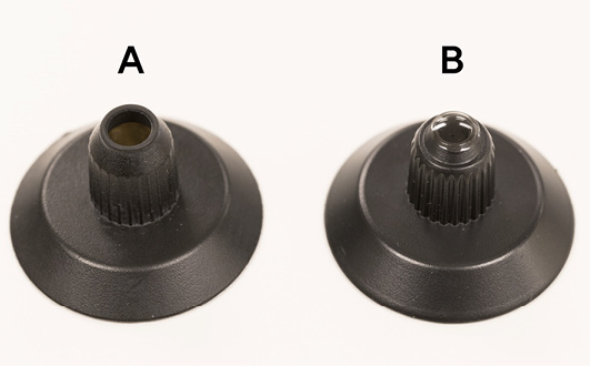
This problem can be solved when a lens stop with a reduced height and a smaller aperture is used, which is available as an accessory for most lensmeters. (Figures 17A and 17B) If a replacement stop is not available, a designated lensmeter can be set aside which is calibrated for measuring the back vertex power of RGP contact lenses. If the optic zone of an RGP contact lens is smaller than the aperture of the lensmeter’s lens stop, the image quality is affected and the power measurement may be compromised.
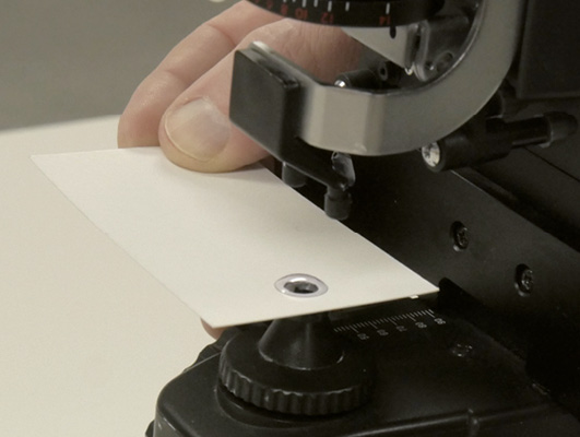
An index card or business card can be modified to decrease the lens stop’s aperture and to hold the RGP contact lens for its power verification (Figure 18).
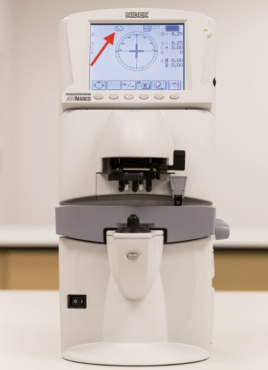
Electronic lensmeters have a special measurement mode for contact lenses. This mode activates automatically when the regular lens holder is replaced with the contact lens measuring holder. The contact lens measurement mode is indicated on the display by an icon, as shown in Figure 19.
Even with a small lens stop, measurement errors can occur in multifocal contact lenses since these lenses have substantial power variations across their optic zones.33
Verification of Lens Thickness
The thickness of an RGP contact lens has an impact on its oxygen transmissibility,34 flexure, position, and comfort.35 Of all the contact lens parameters, center thickness has the smallest manufacturer’s tolerance (Table 1). It can be measured using a variety of mechanical, electromechanical, and optical instruments.
Thickness gauge (mechanical micrometer)
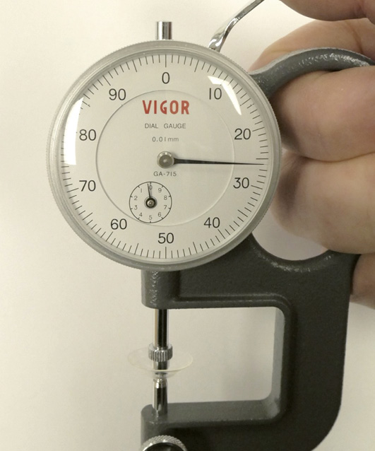
In clinical practice, a thickness gauge is the most common method of determining lens thickness.24 It is a simple mechanical micrometer, which consists of a spring-loaded probe with a rounded tip, connected to a manual lever, and geared to an analog reading scale. After setting the scale to zero via the adjustment screw, the RGP lens is positioned and centered on the gauge, and the probe is carefully lowered onto the lens. The thickness is then read directly from the analog scale. A dial gauge with an RGP lens in place is depicted in Figure 20. Both the center thickness and edge thickness of RGP contact lenses can be measured.
Radiuscope (optical microspherometer)
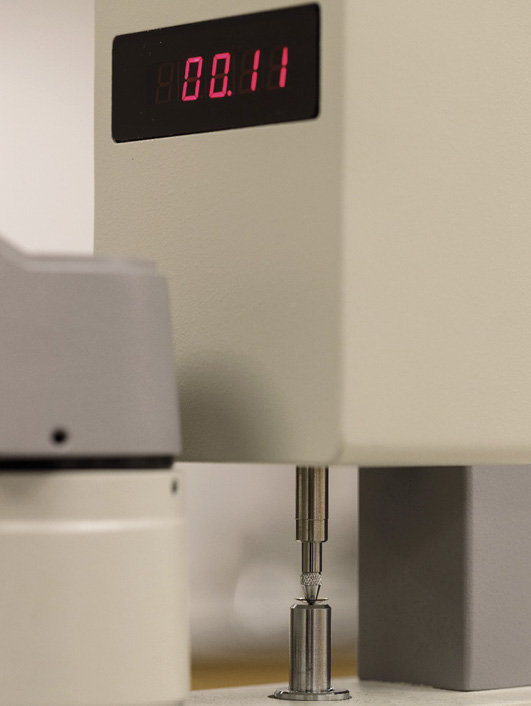
Some radiuscopes are equipped with an auxiliary thickness gauge. To perform the measurement, the measuring scale of the radiuscope is first set to zero. Then, the RGP contact lens is gently positioned with its convex front surface facing downward in the micrometer‘s probe, and the measurement value is read. This is shown in Figure 21. The measurement should be performed carefully to avoid damaging the contact lens with the thin measuring probe
To avoid any possible damage to the lens, the radiuscope may also be used optically to measure the lens thickness. In order to perform this correctly, the lens needs to be completely dry and clean. Unlike when measuring the surface radius, both of its surfaces need to be dry. As shown in Figures 22A and 22B, the contact lens is placed with its concave back surface on the flat edge of the contact lens mount. The microscope is first focused on the front surface, and the scale is set to zero. The microscope is then focused on the image of the back surface. To obtain the lens thickness tc, the scale reading tm is multiplied by the refractive index of the lens material nc, which can be formally expressed by the following equation:
tc = tm · nc
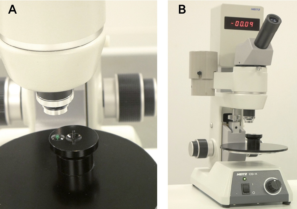
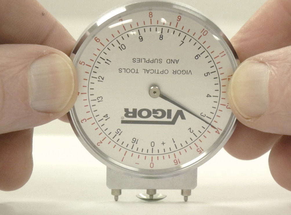
Lens clock (spherometer)
A lens clock is typically used to measure the focal power of front and back surface curves on spectacle lenses. However, it may also be used to measure the thickness of RGP contact lenses. As can be seen in Figure 23, during measurement the lens needs to rest on a flat and clean surface with its concave side up. The lens clock’s middle pin is carefully positioned over the center of the contact lens. Next, the lens clock’s black scale, which indicates positive refractive powers, is read for thickness determination. A step of 1.00 diopter corresponds to a thickness of 0.1 mm. Since the intervals of the scaled markings are set in 0.25 diopter increments, measurements of RGP lens thicknesses can be made in 0.025 mm intervals and estimated for values in between.
Inspection of the Lens Edge (Bevel)
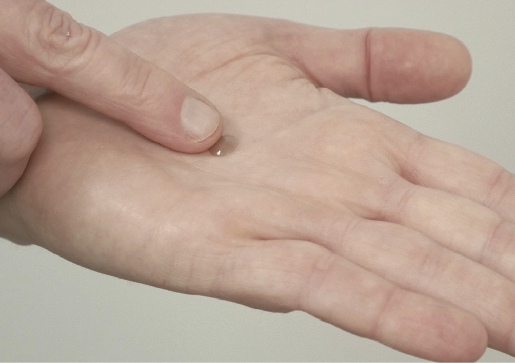
The edge profile of an RGP contact lens has a marked effect on initial patient comfort. One of the most important factors for patient comfort is the shape of the anterior lens edge, which should be well-rounded.36 Before an RGP contact lens is dispensed to a patient, its edge needs to be inspected. A foreign body sensation, irritated eyes, and corneal damage may result from a defective lens edge. The simplest method of edge inspection for a defect is the palm test, where the lens is placed convex side up at the palm of one hand and moved across the palm with the other hand. (Figure 24) A lens with a defect edge does not glide easily but shows some resistance.24 To visually identify any edge defects and measure their sizes, a measuring magnifier, projection magnifier, or biomicroscope (slit lamp) can be used. With either method, the lens is observed from both the frontal and profile perspective. Figure 25 shows the profile perspective of an RGP lens for edge analysis, obtained with a projection magnifier.
Inspection of the Surfaces and Blends
The surface quality of an RGP contact lens is a very important element for fitting success. Scratches, lathe tool marks, etc. influence comfort, visual acuity, wettability, and the potential formation of deposits and films.24 The blending of the peripheral curve system can affect initial comfort, tear exchange, and corneal integrity. Both aspects can be easily evaluated with standard equipment, such as magnifiers and biomicroscopes. The more the lens is blended, the more difficult it will be to identify the transition between different peripheral curves.
Surfaces
To determine the surface quality of an RGP contact lens, a projection magnifier, a stereomicroscope, or a biomicroscope (slit lamp) may be used.24 These instruments allow the variation of magnification, which aids in identifying surface scratches, cracks, deposits, and films. Typically, an initial general assessment is carried out with diffuse illumination at low magnification, followed by detailed observations at higher magnification, direct illumination, and various slit widths.37 This can be seen in Figure 26. In addition, the biomicroscope allows observing the lens wettability in vivo. Contact lens manufacturers usually state the in vitro wettability of their lens materials by specifying wetting angles, but the in vivo wettability is clinically more important. To perform this test with a biomicroscope, the lens is placed on the patient’s eye, fluorescein is instilled, and the break-up time of the pre-lens tear film is evaluated.
Blends
The general quality of the peripheral curve system of an RGP contact lens, as well as blends between different lens zones, can be effectively evaluated by observing the reflex image of a standard indoor fluorescent lamp, known for its suitability due to the extended length of the tube, which provides an extended reflex image.38 To perform this assessment, the lens is held concave side up and observed with a magnifier. By tilting the lens, the reflection of the fluorescent lamp is captured. Due to the presence of peripheral curves, the reflex image will change from center to edge. Well-blended curves result in a very smooth transition. Insufficient blends, deep scratches, and substantial surface damage will give abrupt changes in the reflex image.
Quite suitable for this assessment is also an older instrument, the so-called Burton-Woods lamp, which, in addition to blue fluorescent tubes for evaluating the fit of contact lenses on the eye, also has those that emit white light. The latter are used for assessing the blends between the lens zones. The Burton-Woods lamp contains a magnifier that enables glare-free viewing of a virtual, upright, and enlarged image. An assessment of blends in an RGP contact lens is shown in Figure 27.
Inspection of Other Factors
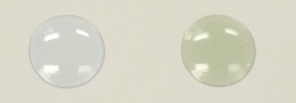
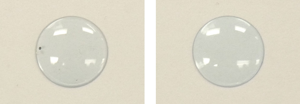
In general, RGP contact lens materials are characterized by features such as flexibility, refractive index, specific gravity, and tint. Except for the tint, these features cannot be easily assessed in a clinical environment. Tints are used to ease the handling of the lens to the wearer and may also be used to help distinguish different lens materials. (Figure 28)
RGP contact lenses may have engravings or marks, for example, dots, lines, letters, or numbers, that can be verified with the naked eye, a magnifier, or a biomicroscope. (Figure 29) This also applies to the height of the segment line in a translating bifocal RGP lens. Furthermore, lens fenestrations can be evaluated in the same way. Of particular interest here is the finish, since a rough fenestration edge may cause corneal irritation.
Conclusion
Manufacturing tolerances for rigid contact lenses are defined by the International Organization for Standardization (ISO) in Standard 18369-2:2017, titled ”Ophthalmic Optics – Contact Lenses – Part 2” and contact lens manufacturers strive to adhere to this standard. Deviations may become apparent during follow-up examinations, either due to age-related parameter changes or lens mix-ups. In addition to thorough documentation, eye practitioners should understand how contact lenses are manufactured, what the relevant tolerance ranges are, and how to verify and inspect lens parameters.
Radiuscopes (optical microspherometers), keratometers, corneal topographers, magnifiers, thickness gauges (mechanical micrometers), V-shaped measuring gauges (V-gauges), biomicroscopes (slit lamps), and lensmeters are the most commonly used instruments in daily practice for verifying parameters of RGP contact lenses.
The verification of surface radii, lens diameters, lens power, and lens thickness and the inspection of surface quality, edge areas, and blends between different lens zones should be performed before fitting and dispensing each contact lens, as well as during regular follow-up examinations. In addition, any parameter modification should be carefully documented.
In clinical practice, the majority of these contact lens parameters can be evaluated relatively quickly and accurately. For RGP contact lenses to be fitted and prescribed successfully, this component of contact lens care is crucial.
Conflict of interest
The authors declare that there is no conflict of interests regarding the methods and devices mentioned in the article.

About Frank Spors
M.S., Ph.D., FAAO - College of Optometry, Western University of Health Sciences, Pomona, CA, USA
application of the oxygen transmissibility of powered contact lenses. CLAO J., 17, 169–172.